 |
 |
 |
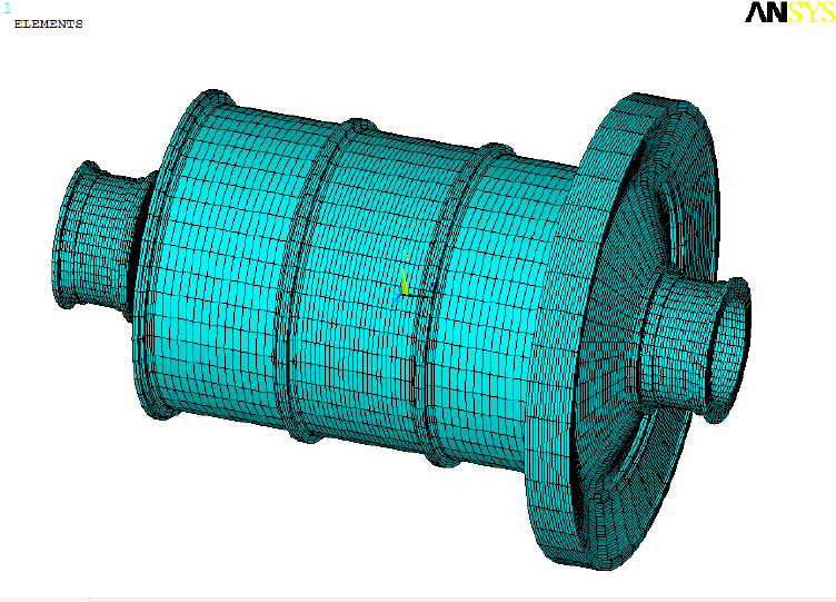
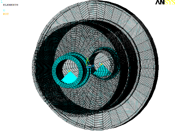
| 1.Finite Element Model of Ball Mill |
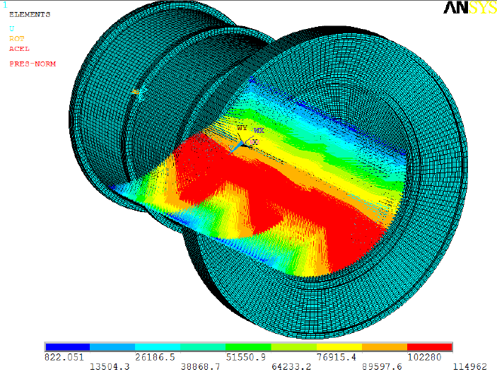
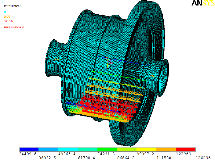
2.Load applied by Ball Mill |
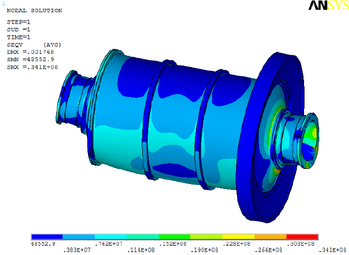
3.Integral Mises Stress Distribution |
 |
 |
 |
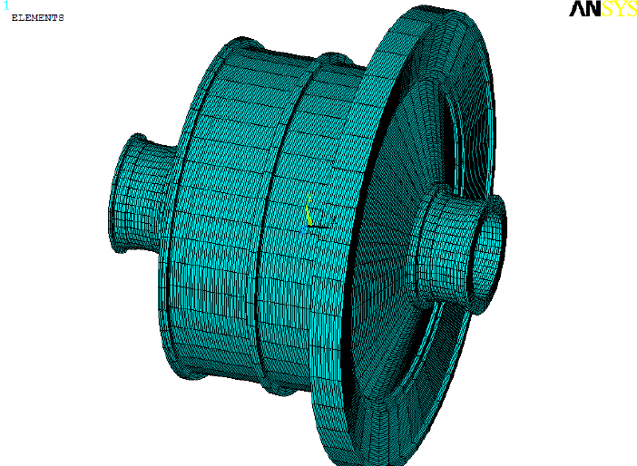
| 4.Finite element model of SAG mill | 5.Restraint imposed on SAG mill | 6.SAG mill applied load |
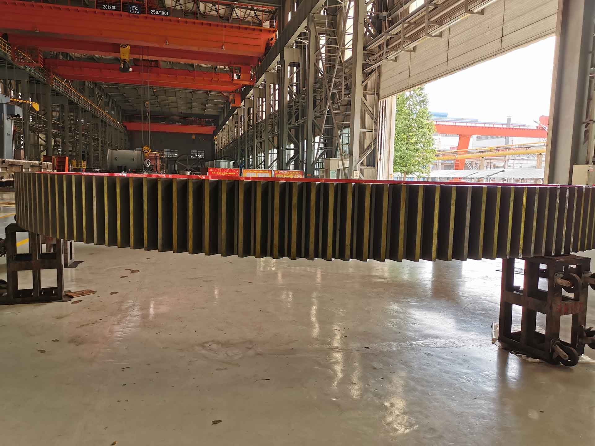
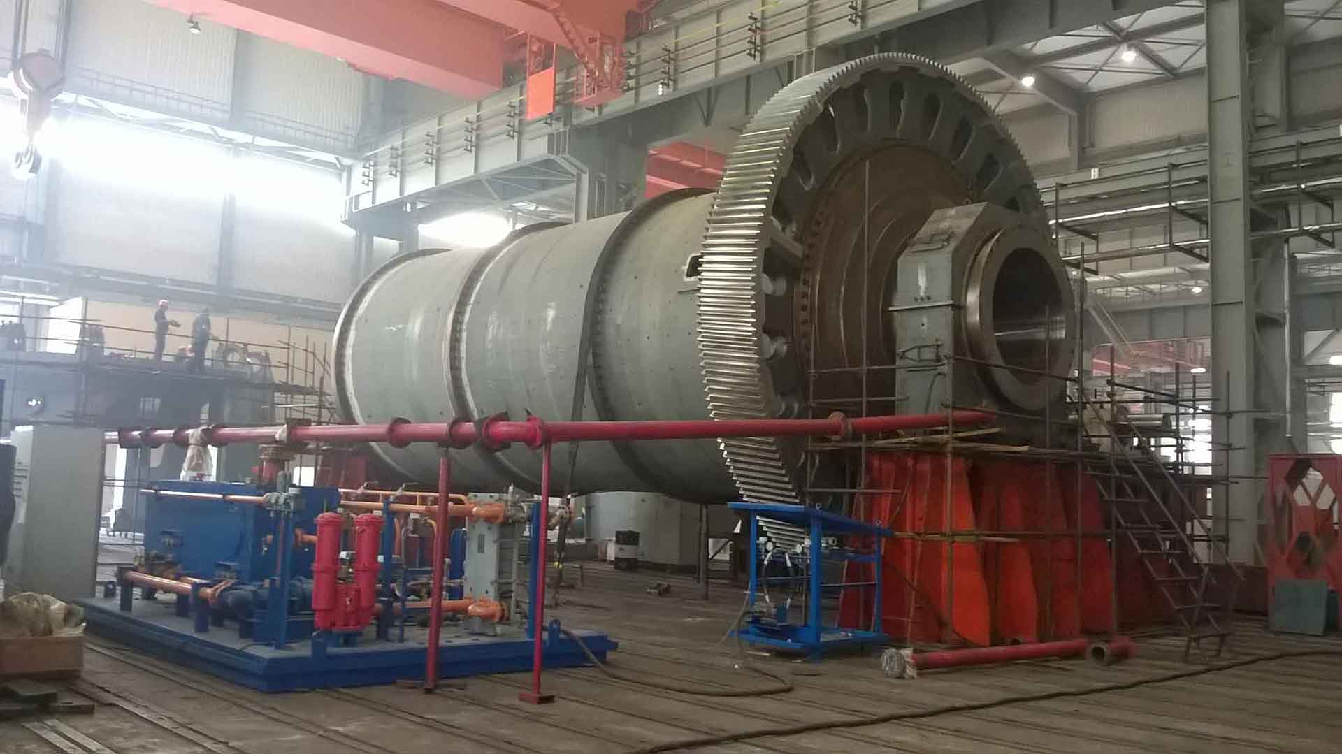
The stress and strain data of the rotary body of the mill under full load, static and material impact conditions are analyzed by using finite element theory and dynamic knowledge, and the stress and strain law of the rotary body of the mill is studied.
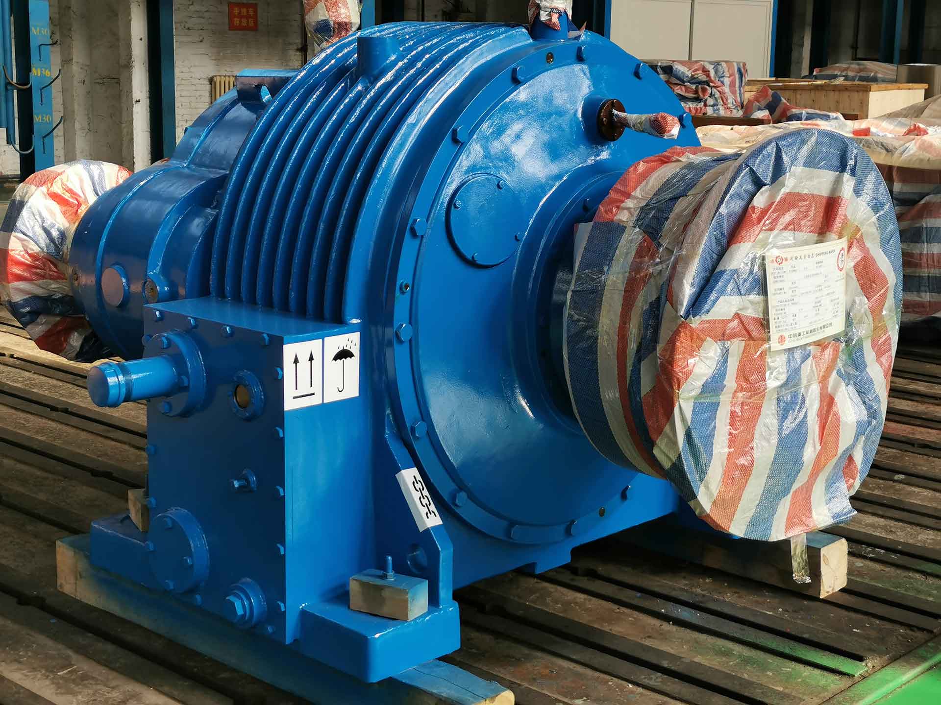
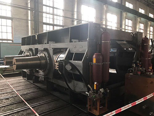
The rotation of the revolving body is driven by the motor through the reducer and the surrounding big gears. The inner part of the cylinder is equipped with proper amount of crushing media and abrasives, which are raised to a certain height under the action of centrifugal force and frictional force and are in the state of throwing or dropping. The grinded material enters the inner part of the cylinder continuously from the inlet port and is crushed by moving crushing media and abrasives. The material is discharged out of the machine by overflow and continuous feeding force for the next process.
■ Modeling
◆ Establishment of Entity Model
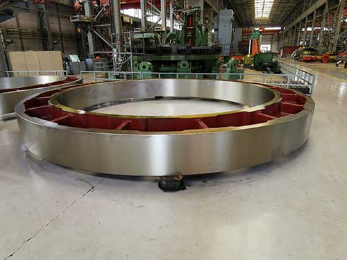
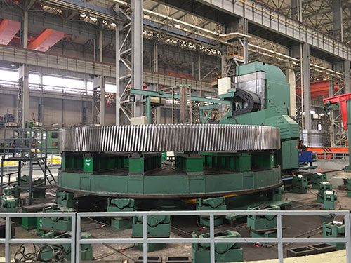
The three-dimensional models of hollow shaft, cylinder and big gear are drawn in CATIA software. Thread holes and small chamfers are removed from hollow shaft, cylinder and big gear in the process of establishing the three-dimensional model. The actual bolt connection between cylinder and end cover flange and cylinder is analyzed. Adhesion treatment with 80% of the joint surface.
◆ Establishment of Finite Element Model
he built assembly model is imported into ANSYS WORKBENCH software. Mesh generation techniques such as rotary sweeping, thinning and local area segmentation are used to ensure that the unit of each part entity is close to the regular hexahedron. Then, the simplified parts are assembled into a whole by node merging and coincidence technology.
■ Boundary conditions
The inlet and outlet ports at both ends of the revolving body are supported by hydrostatic bearings, so they are equivalent to fixed constraints at both ends, and fixed constraints are imposed on the two ends of the model inlet and outlet ports.
The load on the revolving body also changes because of its different working conditions. The working conditions of the mill are as follows:
(I) When the load is still, the revolving body is only subjected to the gravity of the dead weight and the crushing medium and abrasives in the cylinder.
(11) Under full-load rated speed conditions, some of its internal broken media and abrasives, under the action of centrifugal force and friction force, are lifted to a certain height and then thrown into the air, in a state of dropping or dropping, not directly acting on the rotary body. Therefore, the quality of crushing media and abrasives directly acting on the cylinder should be calculated.
◆ Load determination under full load and static condition
Because there is no liner of cylinder and end cap, bushing and identical ring inside hollow shaft in solid modeling, the weight of liner should be added to cylinder and end cap according to equivalent density when applying gravity load, and the weight of bushing and fixed ring inside hollow shaft should be added to hollow shaft according to equivalent density. The structure quality of the mill is obtained by calculation.
◆ Load determination under full load condition
Major technical parameters of ball mill barrel: effective radius of barrel and length of barrel Rotational speed, loose volume mass of crushed media, angular velocity of cylinder, maximum detachment angle
The radial compressive stress of the cylinder can be obtained by calculating the minimum detachment angle.
◆ Finite element analysis results
✔ The maximum strain and maximum strain deformations are obtained from the analysis and calculation results under the static condition of full load of the rotating body of a large mill; the minimum strain and deformation are obtained at the minimum strain.
✔ Stress distribution, maximum stress, minimum stress and minimum stress when the cylinder is fully loaded and stationary.
✔ The maximum strain and maximum strain, minimum strain and deformation of the mill under full-load normal working conditions.