LARGE MINING Mill WEAR LINERS TECHNICAL REQUIREMENTS
1.GENERAL REQUIREMENTS
| SAG Mill |
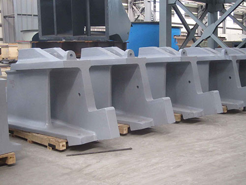
| Feed Head |
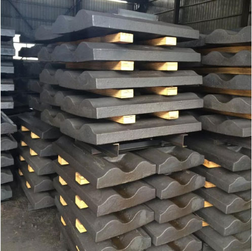
Shell |
Discharge Head |
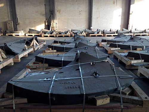
Grate |
| Pearlitic Cr-Mo Steel |
Pearlitic Cr-Mo Steel |
Pearlitic Cr-Mo Steel |
Pearlitic Cr-Mo Steel |
| Martensitic Cr-Mo Steel |
|
|
|
| AG Mill |
| Feed Head |
Shell |
Discharge Head |
Grate |
| Pearlitic Cr-Mo Steel |
High Chrome Iron |
Pearlitic Cr-Mo Steel |
Pearlitic Cr-Mo Steel |
| High Chrome Iron |
Pearlitic Cr-Mo steel |
High Chrome Iron |
Ni Hard |
2.LINER DESIGN
The Contractor shall be responsible for complete liner design, preparation of complete liner drawings and specifications and coordination with the liner supplier as required ensuring proper fit, unless otherwise specified in the contract.
The Contractor shall supply written justification of the liner design, including a Discrete Element Model (DEM) simulation for load trajectory results and expected life on the liners for Approval by the Engineer. When liners in excess of 2000mm long are proposed, the cyclic loading on liners and liner bolts shall also be calculated and supplied to the Engineer for approval.
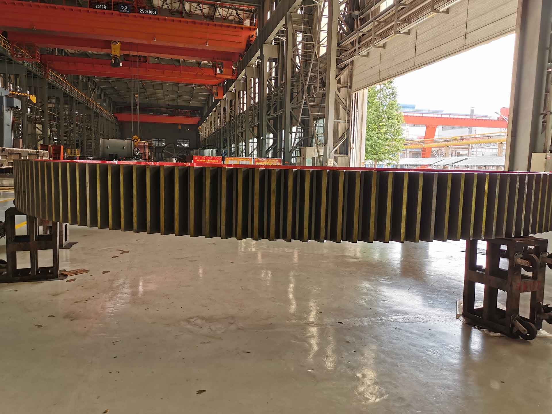
Shell liner configuration shall avoid continuous circumferential joints to prevent formation of pulp raceways and shall ensure that liners do not span over shell flanged joints. The number of different types and sizes of mill liners shall also be minimized. All ball mill liners shall be sized to easily pass through both the feed and discharge openings. All SAG and AG mill liners and grate sections shall be sized to easily pass through the feed end trunnion opening. Each liner and grate section shall include lifting points for handling during installation and replacement.
2.1 Replacement set of liners
The liner supplier shall be responsible for liner drawings and specifications and to ensure proper fit. The supplier shall provide clear written justification of any change or modification to the existing set of liners, including load trajectory and minimal risk of ball impacts on liner.
3.MANUFACTURING
The liners shall be manufactured by any suitable melting process and shall be accurately cast in accordance with the Approved pattern and working drawings.
The liners shall be fettled and dressed and all surfaces prepared for inspection purposes. Fettling of the liner surfaces shall not be done by any thermal process.
The surface of the liners shall be free of adhering sand, scale, cracks, and hot tears. Cracks and hot tears on the working surface shall not be welded, peened, plugged or impregnated.
Every liner shall be fully and uniquely traceable by means of an identification number which defines the relevant drawing number, component number, cast number and the heat treatment batch/procedure. The manufacturer must also be identified on each liner.
3.1Repair
Cast iron and Ni–Hard cast liners shall not be weld repaired.
Pearlitic and martensitic cast liners shall not be weld repaired on the working surfaces including bolting holes.
Weld repairs shall be conducted using qualified procedures and welders qualified in accordance to BS 4570 specification in accordance with the requirement of the material specification.
A weld repair shall be considered major when the depth of the cavity prepared for welding exceeds 20% of the liner thickness or when the extent of the cavity exceeds 25cm2 Major weld repairs shall be documented by means of sketches and photographs, showing the location and dimension of the cavities as prepared for welding. Major weld repairs shall be approved by the Engineer.
4.HEAT TREATMENT
The heat treatment process required to achieve the necessary physical properties in the liner material will be documented and included in the QCP. The heating and cooling rate shall be such as to minimize residual stresses in liners.
4.1.MATERIAL PROPERTIES
The following are minimum requirements. Other materials of construction shall be considered as per Engineer approval.
4.11Chemical composition
when tested in accordance , the chemical composition of the selected material shall comply with the requirements specified in Table 1.
TABLE 1: CHEMICAL COMPOSITION, in % wt
Alloy |
C |
Mn |
Si |
Cr |
Mo |
S |
P |
Ni |
Total residual max |
| min |
max |
max |
max |
min |
max |
max |
max |
High chrome iron ASTM A 532 Class 3
Type A |
2.0 3.3 |
2.0 |
1.5 |
23-30 |
3.0 |
0,04 |
0,04 |
2,5 max |
0,8 max |
| Pearlitic Cr-Mo Steel |
0,8-0.9 |
0.4
1.0 |
0,5
0.8 |
1.9-2.5 |
0.3 |
0,04 |
0,04 |
0,5max |
0,5max |
| Martensitic Cr-Mo Steel |
0.55-0.65 |
0.6
1.0 |
0.4
0.8 |
1.9- 2.5 |
0.3 |
0,04 |
0,04 |
0,5min |
0,5max |
-
Alloy |
C |
Mn |
Si |
Cr |
Mo |
S |
P |
Ni |
Total residual max |
| min |
max |
max |
max |
min |
max |
max |
max |
Ni-Hard
ASTM A 532 Class 1
Type A |
2.8-3.6 |
2.0
max |
0.8
max |
1.4-4.0 |
1.0 |
0,04 |
0,04 |
3,3-5,0 |
0,8 max |
| Wear resistant weldable plate (Hardox, Abrazo, Durostat, Dillidur or Brinar) |
0,20-0,27 |
2
max |
O,7
max |
1,4 max |
0,6 |
0,01 |
0,025 |
1,0 max |
CEV1 0,53
max |
TABLE 2: Physical and Mechanical Properties
Alloy |
Brinell hardness working surface
|
Brinell Hardness 50mm below working surface |
Impact toughness, at 25°C |
Microstructure |
Heat treatment |
High chrome iron ASTM A 532 Class 3
Type A |
600 min
|
540 min |
10J |
Martensite and carbides |
De-Stabilized |
Pearlitic Cr-Mo Steel
|
330- 450 |
315 min |
25J |
Pearlite, ferrite, carbides |
Pearlitized |
Martensitic Cr-Mo Steel
|
425 min |
382 min |
30J |
Martensite, carbides |
Quenched and tempered |
Ni-Hard
ASTM A 532 Class 1
Type A |
600 min |
540 min |
15J |
Austenite |
|
Wear resistant weldable plate (Hardox, Abrazo, Durostat, Dillidur, Brinar)
|
450 min |
450 min |
50 J |
Martensitic |
Quenched and tempered |
Note: 1 Surface of the original casting to a maximum of 3mm below the original surface.