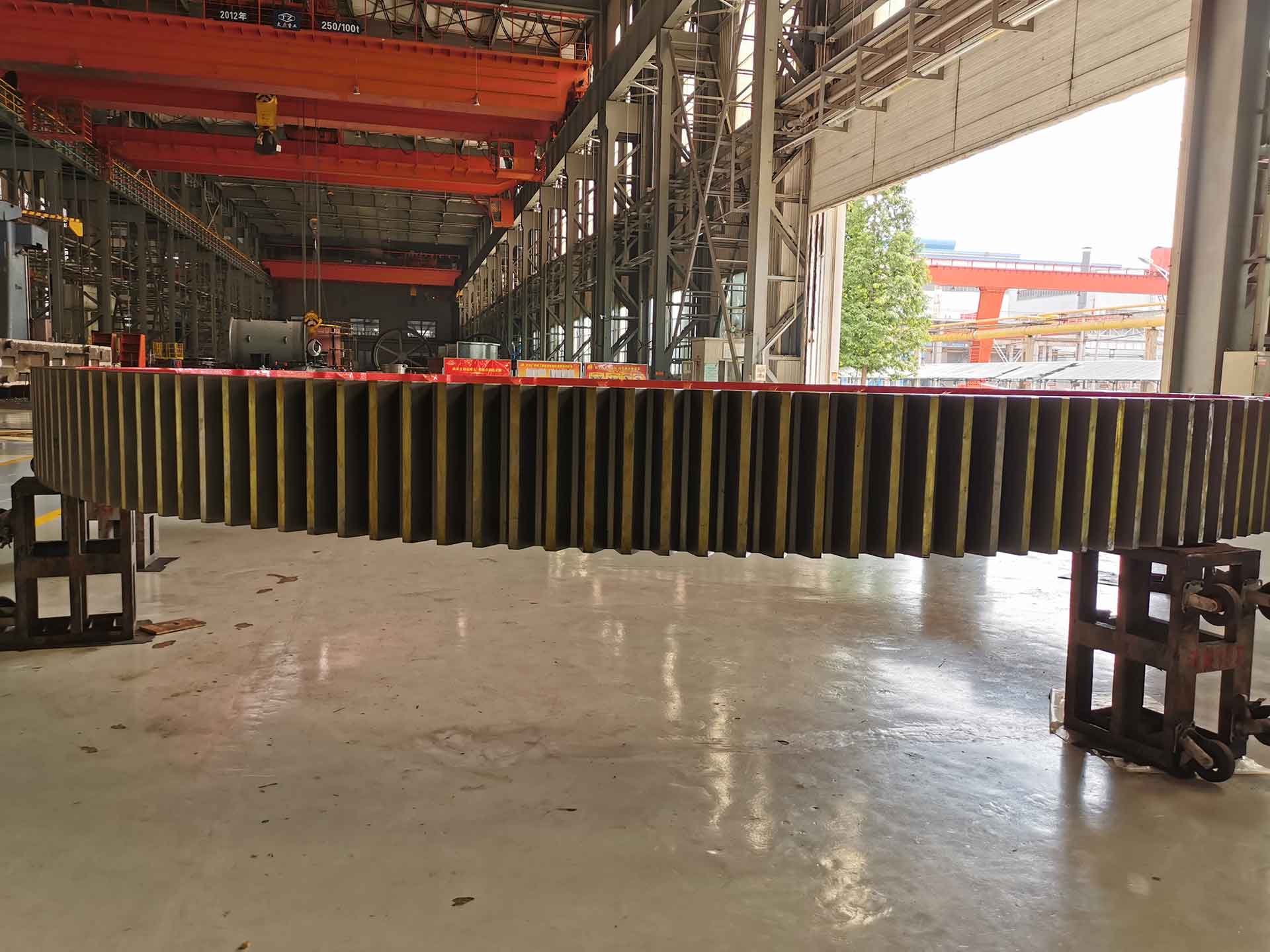
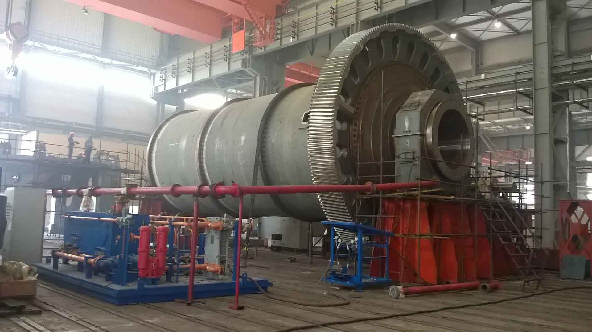
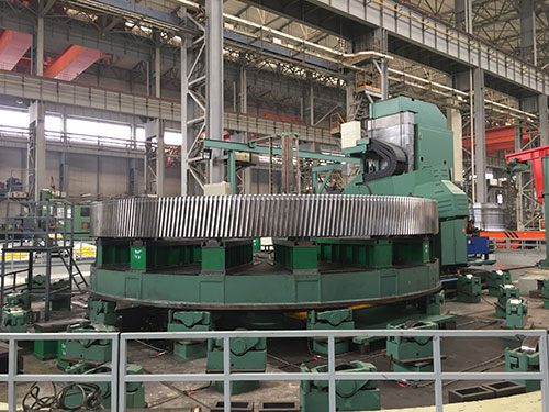
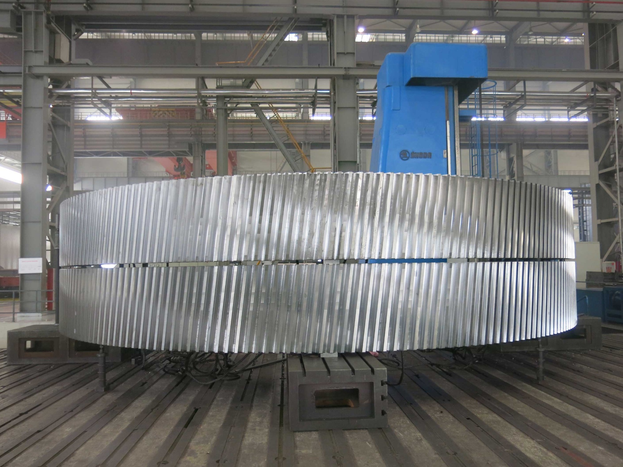
Luoyang Hengin Heavy Technology Co., Ltd.

Luoyang Hengin Heavy Technology Co., Ltd.

Home / Mining Mill Girth Gear / Mill Girth Gear Machining Process
Mill Girth Gear Machining Process
1.Finishing machining 2.Mill Girth Gear Finished Products
 

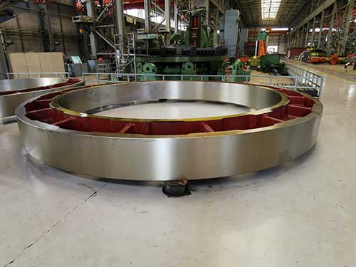
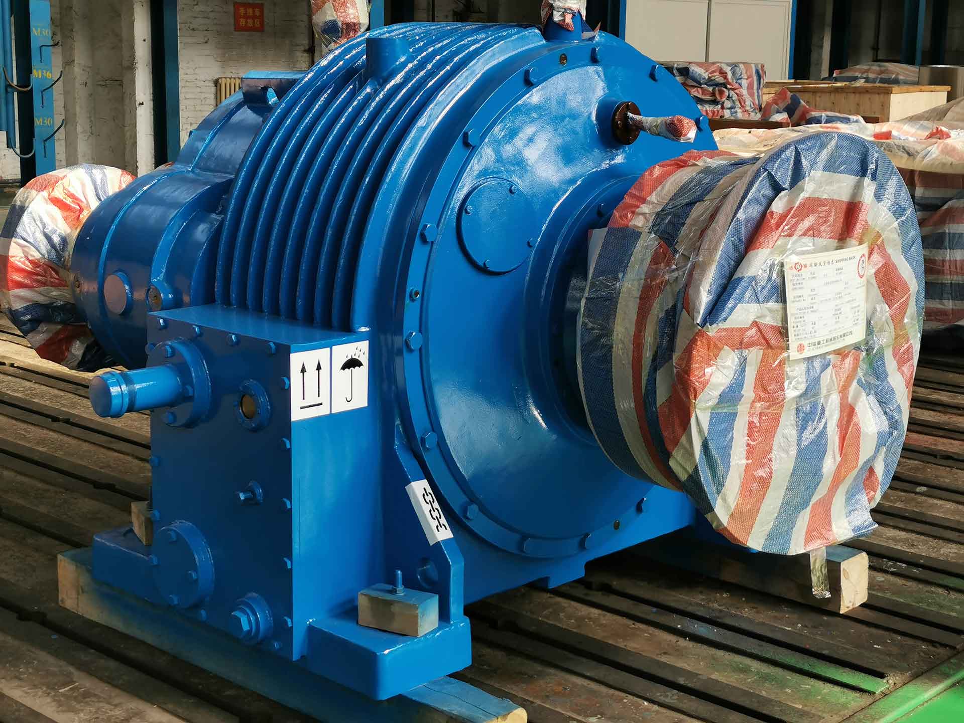
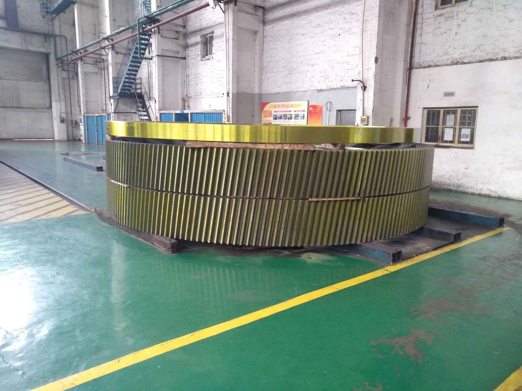
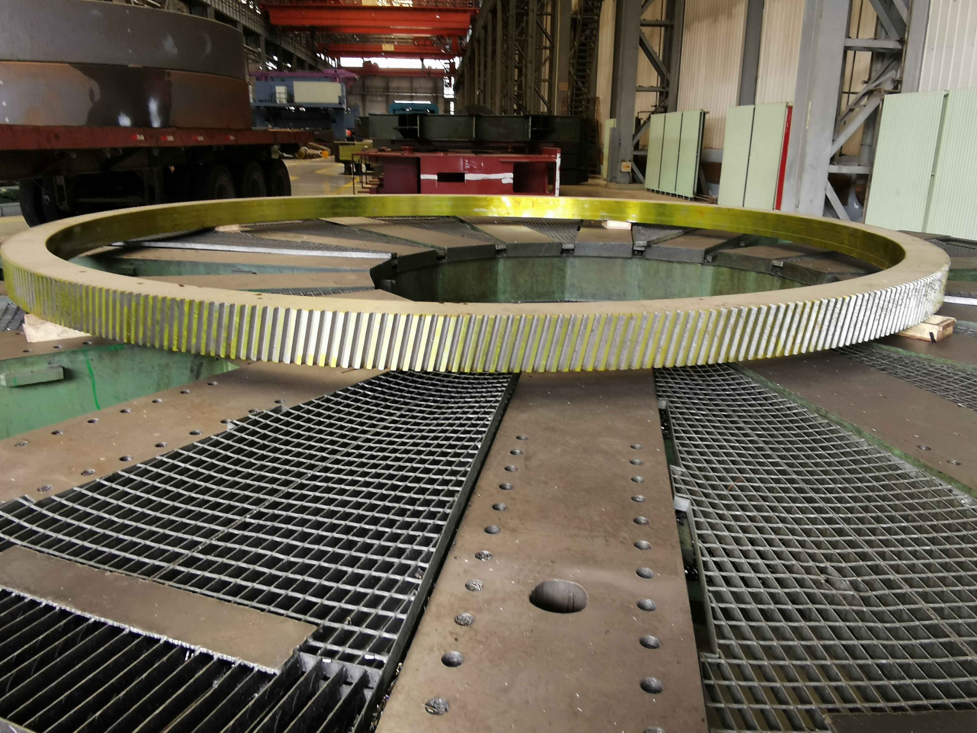
3.Girth Gear Aging Treatment-1
4.Girth Gear Aging Treatment-2
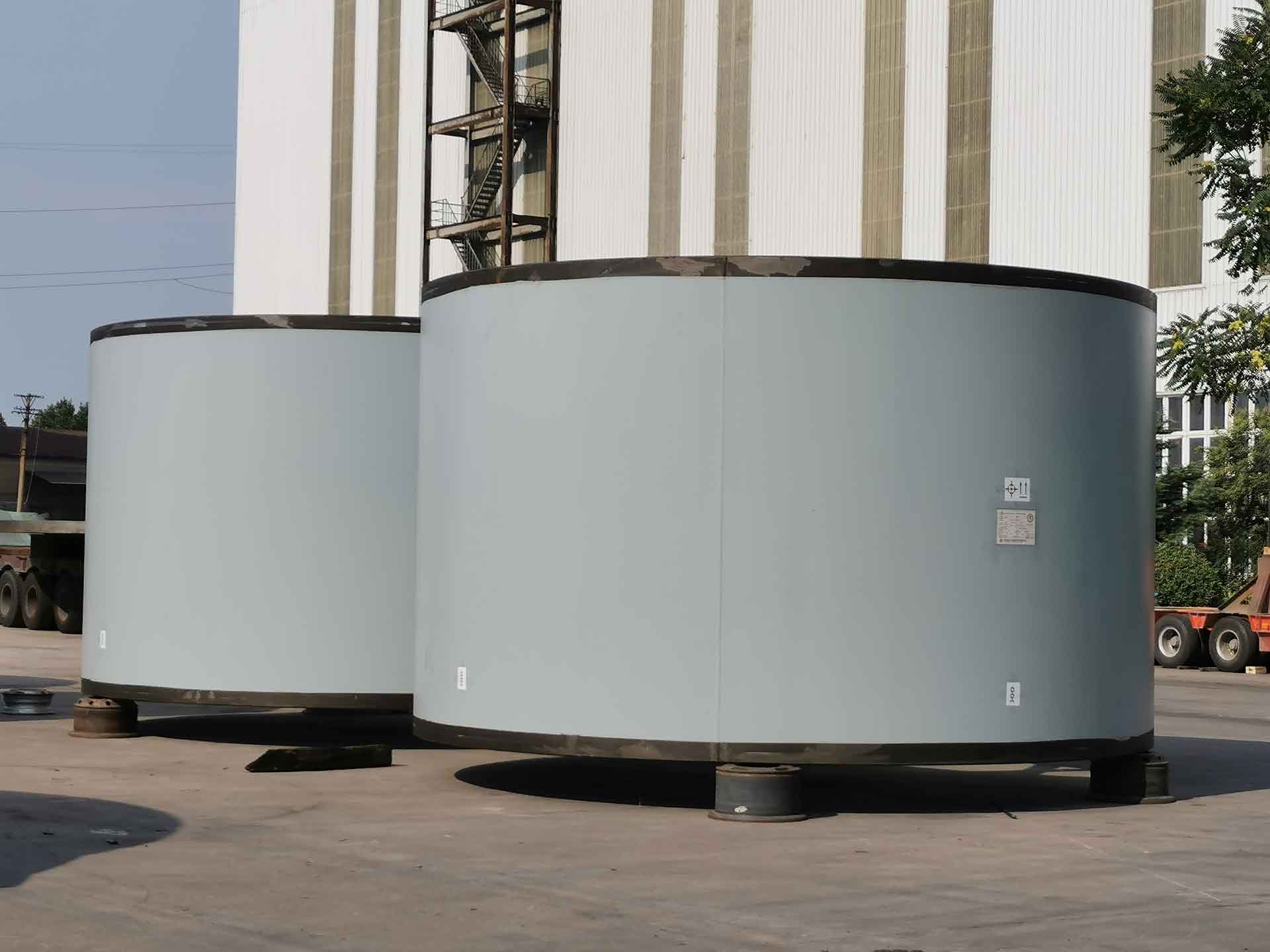
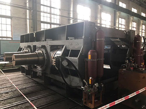
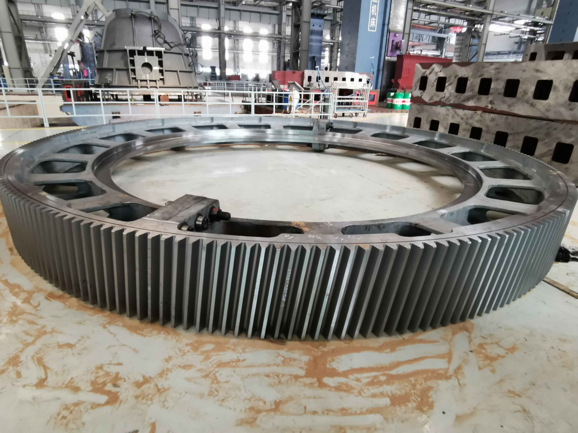
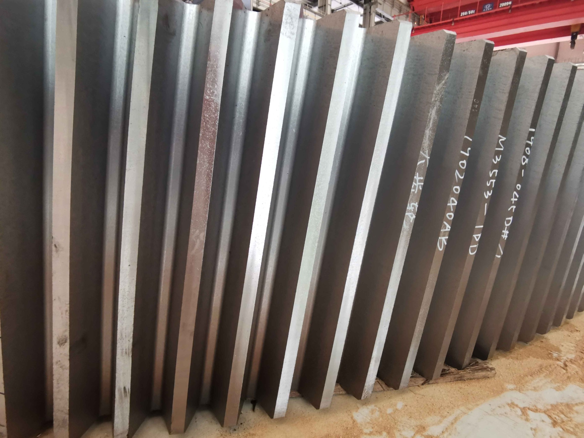
5.Girth Gear Surface
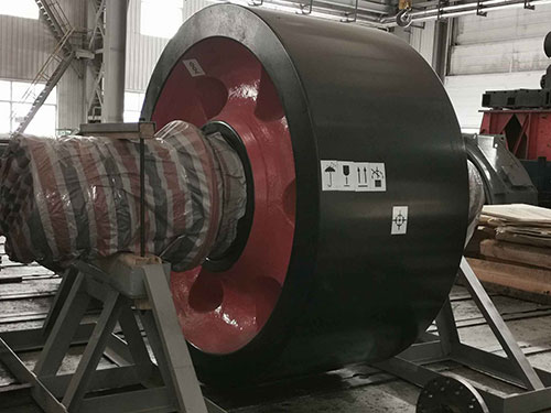
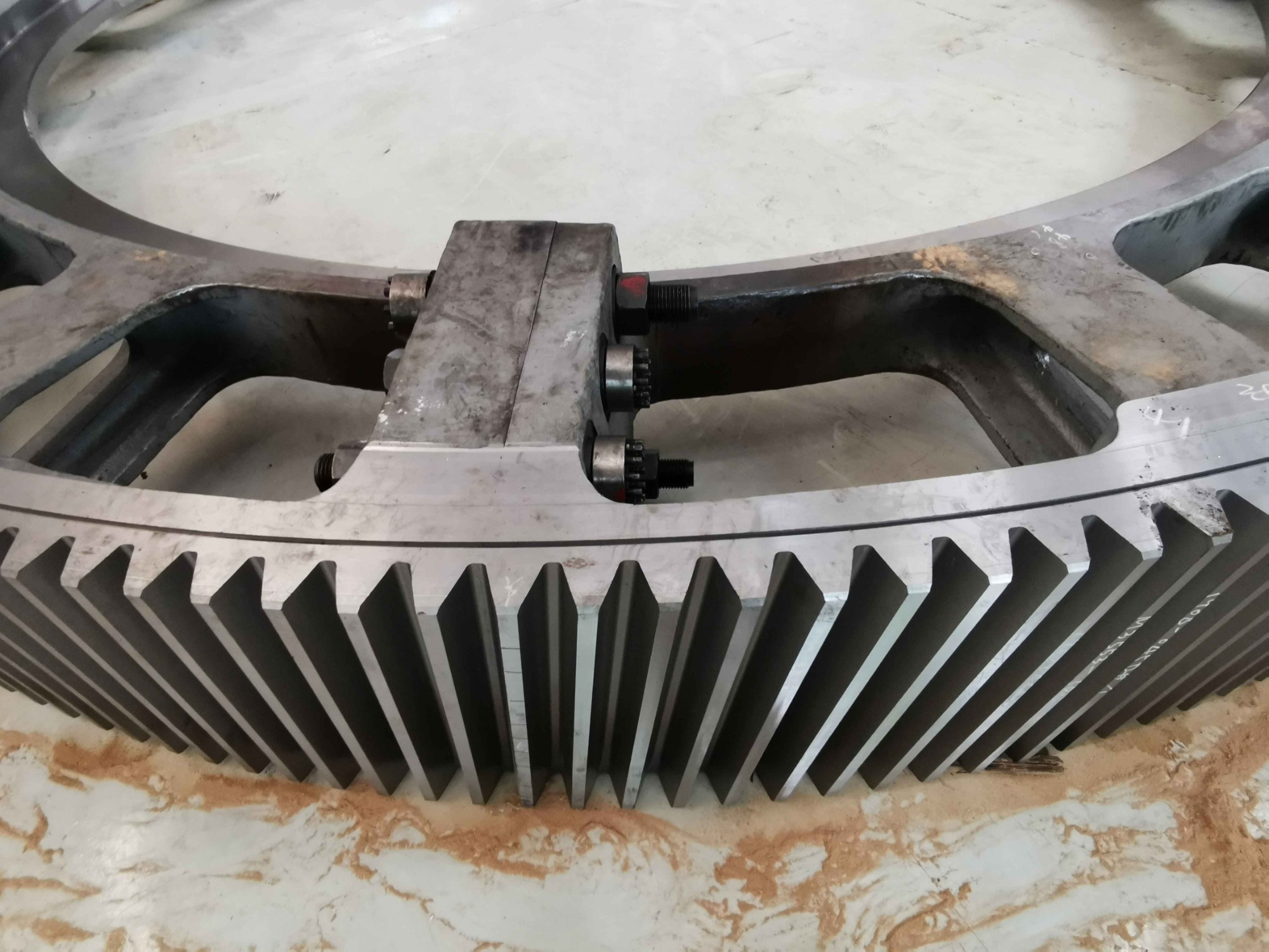
6.Semi-Girth Gear Bolt Connection


■ Blank marking
The center of the circle is determined considering the thickness of the rim and the joint surface to ensure there is sufficient margin for the inner and outer circles, then recording the thickness of the rim and the joint surface.
■ Roughing stage
Check if the girth gear has a dumping phenomenon by a right angle bender and use this result to determine if there is sufficient margin for the lower outer circle.
CNC boring machine: The key is to control the flatness of the horizontal waistline within 1mm, in order to ensure that there is no gap in the joint surface after jointing.
Ordinary boring machine: Due to the production arrangement plan, the rough boring joint surface of the girth gear may be arranged to process by the ordinary boring machine. For the spur gear, the key is to control the flatness of the horizontal waistline within 1mm. For the helical gear, The key is to strictly align according to the joint surface line, and after roughing boring the joint surface, the joint of the workpiece need to be tested to ensure there is no gap in the joint surface, and if there is a gap, it need to be repaired again according to the situation.
■ Rough lathe processing
Find the align level according to the horizontal waist type and the full circle height difference should be controlled within 1mm, especially the horizontal waist type at the joint surface of the split girth gear must be equal. At first, use 2 needles (the distance is 180°) to check that the joint surface goes through the center of the rotary table and after the end face sees the light, check it exactly once. The error must be controlled within 1mm; (when the error exceeds 1mm, the offset between the joint surface of girth gear and center of the table is 1mm/4=0.25mm)
■ Semi-finishing
The center line of the tooth width is determined according to the center of the blank thickness of the 3 unprocessed spoke plate and which is used as the reference for the leveling of the Semi-finishing combined surface and Semi-finishing lathe processing (due to the deformation of the girth gear after normalizing, the scheme of secondary marking and the blanking marking is consistent).The center of the circle is determined considering the thickness of the rim and the joint surface to ensure there is sufficient margin for the inner and outer circles, then recording the thickness of the rim and the joint surface (the recording table is consistent with the roughing). Check if the girth gear has a dumping phenomenon by a right angle bender and use this result to determine if there is sufficient margin for the lower outer circle. When the two halves of the gears are stacked and we need to find the align level according to their respective horizontal waist type and must be controlled within 1 mm. The number of equal height blocks between the two halves of the girth gears is controlled according to the diameter of the girth gear. Relaxing the girth gear during the finishing of the gear, and minimizing the generation of residual stress as far as possible.
After the semi-finishing of the joint surface, the machine tool inspection and the knife-edge inspection method is both used to check the angle and flatness of the joint surface to ensure that the gap of the combination surface after jointing by plug feeler detection is in accordance with the drawings and technical requirements.
  Find the align level according to the horizontal waist type and the full circle height difference should be controlled within 1mm, especially the horizontal waist type at the joint surface of the split girth gear must be equal.
At first, use 2 needles (the distance is 180°) to check that the joint surface goes through the center of the rotary table. The error must be controlled within 1mm; (when the error exceeds 1mm, the offset between the joint surface of girth gear and center of the table is 1mm/4=0.25mm)
Number of support points: the number of support points of girth gear diameter≤ φ11 meters is 16; the number of support points of girth gear diameter ≥ φ11 is not less than 24.
■ Semi-finishing lathe processing 
The support point should be close to the root circle: the rough opening tooth has a large milling force, and the support point should be as close as possible to the position where the cutting force acts, preferably close to the root circle, and the support point position is set to the compression point.
Trial before cutting: For helical gear, try cutting before opening and rolling out the shallow knife tracks on the outer circle. The test is used to check whether the differential roller is correct (equal to check the girth gear helix angle β) and Whether the teeth are correct or not, it is also possible to check whether there is a existence of large half circle and small one on the girth gear.The two half girth gears are stacked, and the number of equal height blocks between the two half girth gears is controlled according to the diameter of the girth gear. Relaxing the girth gear during finish-milling as far as possible to minimize the residual stress. When refine-processing the joint surface, the diameter of the hole is precisely controlled by the floating boring head to avoid single matching and recording size. After the surface is finished by milling, the machine tool and the knife-edge inspection method is both used to detect the angle and flatness of the joint surface to ensure that the gap between the girth gear and the joint surface by a feeler is in accordance with the drawings and technical requirements.
■ Finishing
Before the finishing, the feeler inspection is carried out again on the machine: the girth gear is in a relatively relaxed state on the vertical machine. At this time, the gap of the joint surface should be checked again with a feeler.
 Do not reverse during the finishing process: the riser end face is facing down when card loading, the horn pad is in the position of the riser patch and do not reverse during the finishing process, and the every part is forming during one time finishing process (the riser block position will be removed at the last flange hole processing stage). Number of support points: the number of support points of girth gear diameter≤ φ11 meters is 16; the number of support points of girth gear diameter ≥ φ11 is not less than 24.Four beat records: testing and recording 4 end jump and run jump of the girth gear as required to analyze the changes in end jump and run jump during the girth gear finishing process.


123123
123123123